Measurement of the temperature coefficient
Ozcan Bazkir, Scientific and Technological Research Council of Turkey (Türkiye Bilimsel ve Teknolojik Araştırma Kurumu, TÜBİTAK), Tunus Caddesi No:80, 06100, Kavaklıdere, Ankara
Measurement of temperature coefficients
Temperature coefficients of short-circuit current α(%/0C), open-circuit voltage β(%/0C) and maximum power κ(%/0C) can be determined using solar simulators or natural sunlight by measuring these parameters of a PV module under the constant irradiance level and a range of temperature. The irradiance is provided by the solar simulators, which are the devices that provide illumination approximating natural sunlight. There are two types of simulators can be used as an irradiance source; steady state and flash simulator. Since steady state simulators provide continuous irradiation they can also provide the required heat for heating the PV module under test. On the other hand, flash type simulators since they have pulse type irradiations with a short pulse durations they have a quite low heating effect. Therefore, a different mechanism is needed to vary the temperature of the PV module to be measured. In this type of simulators in general an integrated thermal chamber can be used.
Besides the measurement conditions (constant irradiation and varying PV module temperature) there are some additional requirements when determining the temperature dependent electrical performance parameters of a PV module. These requirements can be listed as follows.
1. Solar Simulator System (Steady State / Flash):
According to the IEC 61215-2 standard, when a solar simulator system is used for determination of electrical parameters of a PV module it must have the following components and specifications:
a. The solar simulator system must have a light source such that in accordance with the specifications of IEC 60904-9 standard it’s spectral match, spatial non-uniformity of irradiance and temporal instability fulfill at least class BBB requirements.
b. The solar simulator system must have a calibrated PV reference device whose short-circuit current versus irradiance is determined in accordance with IEC 60904-2 or IEC 60904-6 standard requirements.
c. The solar simulator system must have a current - voltage (I-V) tracer for the measurements of electrical parameters (the short circuit current, Isc; the open circuit voltage, Voc; the maximum power, Pmax) of PV module. The current - voltage (I-V) tracer should be able to measure the current and voltage of the PV module with an accuracy of ± 0, 2 %.
2.Thermal Chamber:
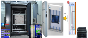
The thermal chamber is needed for changing the temperature of PV module under the test. This unit is only needed for flash type simulators, since the steady state simulator’s radiation sources have heating effect which can be used for heating the PV module. If a thermal chamber is needed to be used with a flash type simulators according to the IEC 60891 standard it must have following accessories and technical specifications:
a. heating and cooling components for controlling the temperature of the PV module by air flow over the required temperature range.
b. A module holder such that its mounting blocks are not be thermally conductive.
c. Temperature sensors for controlling the temperature uniformity inside the chamber.
d. At least four temperature sensors attaching to the back side of PV module for measuring the temperature uniformity over the surface of PV module. Each temperature sensor must have accuracy of ± 1 0C and repeatability of ± 0,5 0C.
3. Attenuation Masks:
According to the IEC 60891 standard for nonlinear PV modules, the determined temperature coefficients are valid at the irradiance level at which the measurements are done and for the linear PV modules they are valid over the irradiance range of ± 30 % of this range. Therefore, to ensure these conditions depending on the linearity of a PV module it will be necessary to carry out the measurements more than one irradiance level. Hence, the attenuation masks are needed for setting the irradiance level of source on the PV module.
Procedure for the measurements of temperature dependent electrical parameters of PV modules
In IEC 60891 standard three methods are defined for the determination of temperature coefficients. In this document the interpolation method, which contrary to first two methods does not need any correction parameters as input, is described. According to the IEC 60891 standard in order to implement interpolation methods, the short circuit current, open circuit voltage and maximum power performance parameters of PV modules have to be measured at a range of temperature at least 30 °C in steps of approximately 5 °C. Then by plotting the performance parameters versus temperature and taking the slopes of these parameters the temperature coefficients can be determined. The procedures for these processes are described as follows:
a. PV module should be mounted to the module holder
b. To record the temperature distribution of PV module, at least four (4) temperature sensors should be mounted to the back side of PV module. These sensors have to be attached directly behind the cells.
c. The electrical output of PV module should be connected to the I-V tracer of simulator.
d. If a steady state simulator is used, for heating the PV module the irradiance level has to be set to a specific value at this stage. For the flash type simulators this can be done after heating process. If a flash type simulator is used, for heating the PV module a thermal chamber need to be used. For this;
· All the doors of thermal chamber must be closed for the heating and cooling the PV module.
· In setting the temperature, it is recommended to set the temperature starting from the lowest temperature value. After setting the temperature inside the thermal chamber wait until the desired temperature stability is achieved.
e. By recording the temperature values at each point the temperature non uniformity has to be evaluated and compared with the IEC 60891 standard requirements (±2 0C). If the calculated non uniformity is less than the standard requirement, then the PV module can be irradiated and the measurements of it’s the electrical performance parameters can be performed.
f. The heating and the measurements of electrical performance parameters should be continued at each 5 °C increments of the PV module temperature for 30 °C temperature range.
g. By acquiring the I-V curves of the module at different temperatures, the temperature dependent values of short circuit current, open circuit voltage and the maximum power can be extracted
h. From the temperature dependent graphs after a least-square linear fit evaluate the slopes using Eqns2.
α = ΔIsc d/ΔT (A/0C) (2.a)
β = ΔVoc d/ΔT (V/0C) (2.b)
Κ = ΔPmax d/ΔT (W/0C) (2.c)
These are absolute temperature coefficients for short-circuit current, the open-circuit voltage and the maximum power respectively. In the data sheets of PV modules in general relative temperature coefficients are given. To convert these temperature coefficients into relative temperature coefficients, any variations in the short-circuit current, the open circuit voltage and the maximum power within the temperature interval are respectively divided by the short circuit current, the open circuit voltage and the maximum power values obtained at STC (Eqns3).
α = 100 • (ΔIsc /Isc)/ΔT (%/0C) (3.a)
β = 100 • (ΔVoc/Voc)/ΔT (%/0C) (3.b)
Κ = 100 • (ΔPmax /Pmax)/ΔT (%/0C) (3.c)
Table 2: Temperature coefficients of electrical parameters of PV module
| Electrical Parameters | Temperature Coefficients | Values |
| Short Circuit Current ,Isc (A) | α | a (%/0C) |
| Open Circuit Voltage ,Voc (V) | β | b (%/0C) |
| Maximum Power , Pmax (W) | κ | c (%/0C) |
Using these parameters in the translation equations given Eqn (1), along with the STC values, the electrical parameters of a PV module can be calculated at different temperatures.
Measurements with a flash solar simulator – Case study
In this section, a case study is carried out to demonstrate typical measurements of the temperature dependent performance of the electrical parameters of the PV module and to calculate its temperature coefficients using a flash type solar simulator measurement system. In order to perform the measurements and to make the calculations correctly, all the stages mentioned in Section 3 which is prepared according to the relevant standards must be fully applied. The procedure for measurements and temperature coefficients using pulse type solar energy simulator is as follows:
· The PV module is mounted to the module holder as shown Figure 1a
· Temperature sensors were mounted to the back side of PV module.
· The outputs of PV module are connected to the I-V tracer of simulator.
· All the doors of thermal chamber are closed
· The thermal chamber is turned on and the temperature was set at 20 0C
· After the desired temperature stability was achieved temperature values from each sensors were recorded (Table 1, Row 1).
Table 1: Temperature distribution over PV module surface
| T1
(°C) |
T2
(°C) |
T3
(°C) |
T4
(°C) |
Tmax-Tmin
(°C) |
Std Req (°C) |
| 20,7 | 20,2 | 20,3 | 20,3 | 0,50 | ±2 |
| 25,9 | 25,3 | 25,8 | 25,6 | 0,60 | ±2 |
| 29,9 | 29,5 | 29,6 | 30,0 | 0,49 | ±2 |
| 34,5 | 34,1 | 34,3 | 34,6 | 0,49 | ±2 |
| 40,4 | 39,8 | 40,0 | 40,2 | 0,60 | ±2 |
| 45,3 | 44,8 | 44,9 | 45,0 | 0,50 | ±2 |
| 50,4 | 49,9 | 49,5 | 50,0 | 0,95 | ±2 |
· Temperature non-uniformity was evaluated and compared with the IEC 60891 standard requirements (±2 0C).
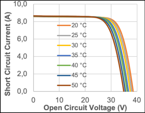
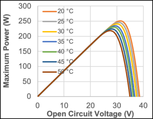
· I-V and P-V curves we recorded as shown in Figure 2
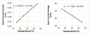
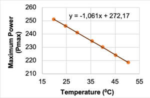
The above process was repeated for 5 °C increments of the PV module temperature until a 30 °C temperature range covered. From the curves above the temperature dependent values of short-circuit current, open-circuit voltage and the maximum power values were obtained. Graphs of short circuit current versus temperature, the open circuit voltage versus temperature and the maximum power versus temperature are presented in Figures 3 and 4.
Table 2: Performance parameters of PV module as a function of temperature
| Module Temperature (°C) | Open Circuit Voltage ,Voc (V) | Short Circuit Current ,Isc (A) | Maximum Power Pmax (W) |
| 19,81 | 38,5656 | 8,5656 | 250,9444 |
| 24,63 | 38,0212 | 8,5789 | 246,0843 |
| 29,40 | 37,4491 | 8,5951 | 241,0297 |
| 35,52 | 36,7381 | 8,6096 | 234,5884 |
| 39,83 | 36,2346 | 8,6223 | 230,2024 |
| 45,21 | 35,5652 | 8,6337 | 224,1263 |
| 50,37 | 34,9455 | 8,6470 | 218,5295 |
From the temperature dependent graphs after a least-square linear fit the slopes were evaluate as follows.
α=ΔIsc/ΔT (A/0C )= (5,6470-8,5656)/ (50,37-19,81) = 0,0027
β=ΔVoc/ΔT (V/0C) = (34,9455-38,5656)/ (50,37-19,81) = -0,1185
κ=ΔPmax/ΔT (W/0C) =(218,530-250,944)/ (50,37-19,81) = -1,061
These are absolute temperature coefficients for short-circuit current, the open-circuit voltage and the maximum power respectively. These temperature coefficients can be converted into relative temperature coefficients:
α=(100*ΔIsc/Isc)/ΔT (%/0C) = ((5,6470-8,5656)/ 8,5779)/(50,37-19,81)= 0,03
β=(100*ΔVoc/ Voc)/ΔT (%/0C) =((34,9455-38,5656)/38,0212)/(50,37-19,81) = -0,31
κ=(100*ΔPmax/Pmax)/ΔT (%/0C) =(218,530-250,944)/246,084)/(50,37-19,81) =-0,43
Table 3: Temperature coefficients of electrical parameters of PV module
| Electrical Parameters | Temperature Coefficients | Values |
| Short Circuit Current ,Isc (A) | α | 0,03 (%/0C) |
| Open Circuit Voltage ,Voc (V) | β | -0,31 (%/0C) |
| Maximum Power , Pmax (W) | κ | -0,41 (%/0C) |
Using these parameters in the translation equations given Eqn1, along with the STC values the electrical parameters of a PV module can be calculated at different temperatures.
For T= 10 0C
Isc,c = Isc [1 + α(T2 – T1)]
Isc(10 0C) = 8,5789*[1+(0,03/100)*(24,63-10)] = 8,5412 A
Voc,c = Voc [1 + β(T2 – T1)]
Voc(10 0C) = 38,0212*[1+(-0,31/100)*(24,63-10)] = 39,7456 V
Pmax,c = Pmax [1 + κ(T2 – T1)]
Pmax(10 0C) = 246,084*[1+(-0,41/100)*(24,63-10)] = 260,85 W
For T= 50 0C
Isc,c = Isc [1 + α(T2 – T1)]
Isc(50 0C) = 8,5789*[1+(0,03/100)*(24,63-50)] = 8,6442 A
Voc,c = Voc [1 + β(T2 – T1)]
Voc(50 0C) = 38,0212*[1+(-0,31/100)*(24,63-50)] = 35,0309 V
Pmax,c = Pmax [1 + κ(T2 – T1)]
Pmax(50 0C) = 246,084*[1+(-0,41/100)*(24,63-50)] = 240,49 W
REFERENCES
IEC 60891, Photovoltaic devices – Procedures for temperature and irradiance corrections to measured I-V characteristics
IEC 61215-2, Terrestrial photovoltaic (PV) modules - Design qualification and type approval - Part 2:Test procedures
IEC 60904-9, Photovoltaic devices – Part 9: Solar simulator performance requirements
IEC 60904-10, Photovoltaic devices – Part 10: Methods of linearity measurement
IEC 60904-2, Photovoltaic devices – Part 2: Requirements for photovoltaic reference devices
