Reference devices
Ingo Kroeger
Physikalisch-Technische Bundesanstalt (PTB), Bundesallee 100, 38116 Braunschweig, Germany
Summary of reference cell properties, importance, different types, what is their purpose and how are they used.
For calibration measurements of solar cells or PV modules the irradiance level can be determined with a reference device. IEC standard 60904-2 [1] defines these as follows:
“Reference solar devices are specially calibrated devices which are used to measure natural or simulated irradiance or to set simulator irradiance levels for measuring the performance of other solar devices having similar spectral response, optical characteristics, dimensions and electrical circuitry.”
This definition follows the idea that measurement uncertainties can be kept as low as possible, if the reference device and the device under test are as similar as possible so that most systematic measurement uncertainties related to the device properties cancel out. This covers exemplary:
- If the spectral irradiance responsivity of the DUT and the reference are identical, the spectral mismatch correction factor according to IEC 60904-7 [2] becomes unity, even if the solar simulator spectrum is poorly matched to the AM1.5g spectrum
- If the size and the non-uniformity of the DUT and the reference are identical the non-uniformity correction of the solar simulator becomes negligible, even if the non-uniformity of the solar simulator is poor.
- If the optical characteristics of the DUT and the reference are identical, systematic measurement deviation arising from interreflections can be avoided.
This principle is applied for industry type “golden” reference solar cells and modules that are used in industry for production lines and that are calibrated by testing and calibration laboratories. Hence these “golden” reference solar cells and modules are well characterized, pre-aged and long term stable devices out of the manufacturing batch. The disadvantage of “golden” reference solar cells and modules is the relatively high measurement uncertainties that can be assigned to these devices that are limited by the state of the art calibration methods.
However, there is a second class of reference solar cells: the world photovoltaic scale (WPVS) reference solar cells. The purpose, its requirements and the design is described by Osterwald et al. [3].
The WPVS reference solar cells are 2x2 cm² solar cells made from mono-crystalline float zone silicon encapsulated in silicone, epoxy or EVA with a durable glass window. The solar cell is electrically connected to female LEMO connectors that are fixed on the side of the package housing using 4 wire technique. On the side of the housing there must be printed or engraved a unique and permanent ID. Usually a Pt100 thermal resistor is attached to the backside of the solar cell allowing a direct measurement of the solar cell temperature. The solar cell is electrically isolated but in good thermal contact to the metal housing in order to enable effective cooling of the solar cell via the backside of the package upon irradiation. The advantage of these reference solar cells are their robustness in handling (due to the housing), their long term stability (due to the encapsulation), their reproducibility (due to the standardized connectors) and the possibility of calibration with very low measurement uncertainty using primary calibration methods (see Module 1 – Lesson 1 “Introduction to PV module power measurements”). The disadvantage of the WPVS reference devices is that they generally are not perfectly identical to the devices under test (industrial type solar cells or modules), so that the accuracy of the calibration methods and proper correction for measurement deviations becomes very crucial.
Additionally, there are options of optically filtered reference solar cells. In these cases, the glass window in front of the solar cell is replaced by a transmission filter in order to modify the spectral responsivity of the silicon device to better match the spectral responsivity of the DUT, e.g. for thin film technologies.
Classification, suppliers, certificates, Standards’ require.
The general requirements for a reference device according to IEC 60904-2 are stable photovoltaic characteristics and linear variation of the output signal with irradiance.
Suppliers of reference solar cells are:
- Fraunhofer ISE:
https://www.ise.fraunhofer.de/en/rd-infrastructure/accredited-labs/callab/wpvs-reference-cells.html
- PVMeasurements:
http://www.pvmeasurements.com/I-V-Health/calibrated-photovoltaic-reference-cells.html
- Konica Minolta:
- PRC Krochmann:
http://www.prc-krochmann.com/index.php/reference-solar-cells
- Solarmer:
http://solarmer.com/solar-reference-cell/
- Abet Technologies
http://abet-technologies.com/pv-iv-measurement-systems/reference-cells/
- ReRa Solutions
https://www.rerasolutions.com/product-category/solar-reference-cells/
- Photoemission
http://www.photoemission.com/referencecells.html
…and probably many more.
The requirements of the WPVS reference solar cell are as aforementioned described by Osterwald et al. [3]
Case study: example reference cell, characteristics, calibration
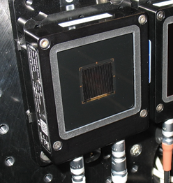
A good example for a reference solar cell is shown in Figure 1. In the centre there is a 2x2 cm² solar cell made from mono-crystalline float zone silicon encapsulated with a durable glass window. The solar cell is electrically connected to female LEMO connected to the bottom. On the left side of the housing there is the printed ID as well as the name of the manufacturer and are marking of the physical position of the cell within the housing.
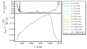
The coloured graphs in Figure 2 show the absolute differential spectral responsivity (DSR) of this reference solar cell. These curves have to be taken, if the reference device is used as a reference for a DSR facility measuring the DSR of a DUT.
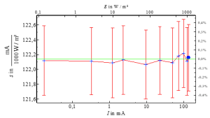
The spectral irradiance responsivity (SR) is shown as dashed line. The SR drops to zero at 280 nm and at 1200 nm. The short circuit current of this cell is 122,14 mA. This SR curve has to be taken for the spectral mismatch correction if this reference device is used as a reference for a solar simulator measuring the short circuit current of a DUT. The irradiance level of the solar simulator has to be adjusted to the short circuit current of this reference. The non-linearity of the device is better than 0.1 % as shown in Figure 3.
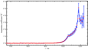
Figure 4 shows the spectral temperature coefficient of this silicon reference solar cell. This graph shows the percentage change of the spectral responsivity per Kelvin temperature difference from 25°C. This correction has to be applied to the spectral responsivity, if the reference cell is operated at different temperatures. A weighting of this function with the SR of the device and the AM1.5g spectrum leads to a temperature coefficient of the short circuit current of 680 ppm/K. This correction has to be applied to the short circuit current, if the reference cell is operated at different temperatures.
References
[1] IEC 60904-2:2015, Photovoltaic devices - Part 2: Requirements for photovoltaic reference devices
[2] IEC 60904-7:2008, Photovoltaic devices - Part 7: Computation of the spectral mismatch correction for measurements of photovoltaic devices
[3] Osterwald, C. R., Anevsky, S. , Bücher, K. , Barua, A. K., Chaudhuri, P. , Dubard, J. , Emery, K. , Hansen, B. , King, D. , Metzdorf, J. , Nagamine, F. , Shimokawa, R. , Wang, Y. X., Wittchen, T. , Zaaiman, W. , Zastrow, A. and Zhang, J. (1999), The world photovoltaic scale: an international reference cell calibration program. Prog. Photovolt: Res. Appl., 7: 287-297.
![Figure 1: Layout and circuit diagram of a WPVS reference solar cell [3]](/images/thumb/e/e2/Layout_and_circuit_diagram_of_a_WPVS_reference_solar_cell_.png/300px-Layout_and_circuit_diagram_of_a_WPVS_reference_solar_cell_.png)
![Figure 1: Layout and circuit diagram of a WPVS reference solar cell [3]](/images/thumb/5/50/Layout_and_circuit_diagram_of_a_WPVS_reference_solar_cell.png/300px-Layout_and_circuit_diagram_of_a_WPVS_reference_solar_cell.png)


