Energy Rating
George Koutsourakis1, James Blakesley1, Ana Gracia Amillo2, Robert Kenny2, Juan Lopez-Garcia2, Ruben Roldan Molinero3, Gabi Friesen3
1National Physical Laboratory (NPL), Hampton Road, Teddington, Middlesex, TW11 0LW, United Kingdom
2European Commission, Joint Research Centre (JRC), Ispra (Va), Italy
3University of Applied Sciences and Arts of Southern Switzerland, SUPSI-PVLab, Campus Trevano, 6952 Canobbio, Switzerland
Introduction
Purpose of Energy Rating
Photovoltaic (PV) modules are currently sold on the basis of a power rating. This rating, often referred to in units of watt-peak (Wp), is the maximum power output, Pmax,STC, of a module measured under standard test conditions (STC) of 1000 W m-2 irradiance, 25 °C module temperature and air-mass 1.5 global (AM1.5G) spectrum. These conditions are defined by the IEC 60904-3 standard [1]. However, in most cases the quantity that is most important to the purchaser is the total expected energy output over the period of operation. In principle, this should be proportional to a module’s peak power (1): [math]\displaystyle{ E_{mod}=\frac{P_{max,STC}}{G_{STC}}H_p.MPR }[/math]
where [math]\displaystyle{ E_{mod} }[/math] is the module energy yield, [math]\displaystyle{ G_{STC} }[/math] = 1000 W m-2 is the irradiance at STC and is the total in-plane insolation over the period of operation. The efficiency of any module is strongly dependent on module temperature, irradiance, solar spectrum and angle of incidence [2][3]. In normal operation, all of these conditions differ from STC. The dimensionless module performance ratio (MPR) is introduced into the above equation to compensate for these effects. It indicates how well a module performs in actual operating conditions relative to STC. Typical annual MPR values for conventional modules range from 0.8 to 1.0 and depend on the choice of module and location. The performance ratio of different modules mounted in the same location over the same period may vary by as much as 10 – 20 % averaged over a year, depending on the location’s meteorological features and the module’s performance parameters.
Therefore, when selecting modules to optimise the value of a system, it is important to consider differences in MPR between module types for the target climate. The new set of standards, IEC 61853 [4]–[7], provides a standardised method for energy rating of PV modules that enables an estimate of MPR for certain reference climates. Crucially, these energy ratings shall be reported with associated uncertainties, which provide much needed information about the reliability of measurements used to calculate the energy ratings. There are many other factors connected to the site, installation, maintenance (inverter losses, soiling, shading, etc.) of a system that also affect performance. However, module energy rating is limited to module-specific factors (temperature, irradiance, angular and spectral effects) that enable a distinction between different modules located in the same site, and do not address these installation-specific factors that will, in general, affect all modules equally.
Standard energy rating involves performing a comprehensive series of measurements on modules across a range of operating conditions. These are combined with a defined model to produce an estimate of the energy output for a set of standardised reference climates. The use of standard reference climates allows a fair comparison between different modules without introducing variability from the choice of climate. Their use also means that the uncertainty in energy rating is considerably lower than the uncertainty in MPR for a specific location, as the latter must include uncertainties in site-specific influences as well as uncertainty in local climate forecasting. However, it must be stressed that energy rating is a tool for differentiating the relative performance of different modules, but it is not the same as an energy yield forecast for a specific site (for which the above-mentioned factors, such as soiling, degradation of components or shading, should be accounted).
Energy yield and Energy rating
It is important at this point to clearly distinguish between energy yield and energy rating since these two concepts are often confused and even used synonymously.
Energy yield is the measurement of or an estimate of the energy produced by a specific PV system, designed and constructed in a particular way and located in a particular location. It requires specific data of the mounting type (fixed, tracking system, open rack or building integrated) and the location, since for the prediction of the energy yield it is necessary to account for the presence of shadows, dust or snow. It requires several years of meteorological data, typically at least 10 years, in order to have a representative estimate for that particular system and location. This long-term performance estimate requires also taking into consideration the PV module's degradation. The units of the energy yield are kWh per unit of time, normally year or the PV system lifetime.
On the contrary, energy rating is a simplified measure of how a given module type will perform in a generic site with a reference climate and it is normally calculated considering a single year of data. It is intended to enable a performance comparison between devices or technologies, but it does not provide an accurate yield estimation as it does not consider site specific aspects, system effects, soiling or module degradation.
The energy rating performance comparison is not based on the estimated energy yield (kWh) but on the so called "Climate Specific Energy Rating" parameter. The CSER is the ratio of the calculated energy yield of a PV module under certain climate conditions to the energy yield that would have been obtained if the module efficiency would have been the one measured under Standard Test Conditions (STC: module temperature of 25 °C, 1000 W m‑2 of in-plane irradiance with a spectral content as defined in the IEC 60904-3 [1]). The CSER is a dimensionless value defined as (2): [math]\displaystyle{ CSER=\frac{E_{mod,year}\bullet G_{ref}}{P_{max,STC}\bullet H_p} }[/math] where Emod,year is yearly energy output (kWh/year), Gref is equal to 1000 Wm-2 as the irradiance applied at STC to measure the maximum power at STC (Pmax, STC). Hp is the yearly global in-plane irradiation (kWh m-2 year-1) which is provided in part 4 of the standard for each reference climatic region. The methodology and the measurements required in order to calculate CSER for a given PV module type/batch is described in the following sections.
Module measurements for Energy Rating
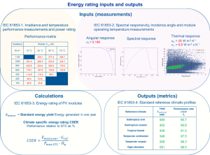
The IEC 61853 standard that describes the Energy Rating procedure for PV modules consists of 4 parts:
- IEC 61853-1 describes requirements for evaluating PV module performance in terms of power (watts) rating over a range of irradiances and temperatures.
- IEC 61853-2 describes test procedures for measuring the performance effect of angle of incidence; the estimation of module temperature from irradiance, ambient temperature and wind speed; and impact of spectral response on energy production.
- IEC 61853-3 describes the calculations of PV module energy (watt-hours) and CSER ratings.
- IEC 61853-4 describes the standard meteorological reference conditions for six representative climate zones for which the energy rating should be calculated.
IEC 61853-1. Irradiance and temperature performance measurements and power rating
IEC 61853-1 describes the methodology to measure the PV module power at maximum power of operation (Pmax) at various levels of irradiance and module temperature (along with ISC, VOC and VMPP for each condition). These measurements can be obtained outdoors or indoors using solar simulators. The results from these measurements are used in IEC 61853-3 for calculations of energy rating. Some energy yield modelling software also accept these measurements as input parameters that may lead to more accurate system yield predictions.
The required measurements defined below are applied to three randomly selected PV modules from the specific batch under test. The selected PV modules will have to be pre-conditioned/stabilised, depending on the requirements of the given PV module technology. The purpose of the measurements is to determine the impact of irradiance and temperature on module performance since the energy yield of photovoltaic devices directly depends on module temperature and incident irradiance level.
As a result of the required measurements separate tables as the one presented In Table 1, for the PV module parameters ISC, VOC, Vmax and Pmax are filled. Measurements should be acquired at irradiances and temperatures specified in the table. Any translation of I-V curves from the actual irradiance or temperature values to the values prescribed by the tables can be performed in accordance with IEC 60891 [8], nevertheless, any such interpolation should be over a range of no more than 100 W m–2. The set of measuring points are shown in Table 1. The irradiance spectral distribution should correspond to AM1.5G as described in [1].
The required measurements at different conditions in order to create Table 1 can be acquired outdoors with natural sunlight or indoors using a solar simulator. For outdoor measurements a tracker or a fixed position for the sample can be used. Shades and meshes can be used to control temperature and irradiance levels in order to fill in the table above. Temperature measurements at multiple positions at the back of the module are advised in order to acquire the average, while a matching reference cell for irradiance measurements is crucial. Similar considerations are taken into account when using indoor measurements with a solar simulator. IEC 61853-1 includes all the detailed technical specifications regarding the procedures for acquiring the above measurements and filling the table below.
TABLE 1
IEC 61853-2. Spectral responsivity, incidence angle and module operating temperature measurements
Apart from different irradiance levels and different operating temperatures, PV modules in the field also experience differences in angle of incidence of irradiance and variations of the spectral irradiance from AM1.5G. The aim of IEC 61853-2 is to define the procedures for measuring these effects and to determine the operating temperature of a module for a given set of ambient and mounting conditions and measure the spectral responsivity of the module. The set of parameters that these measurements will deliver are used for the energy rating calculations which are described in IEC 61853-3.
The spectral responsivity of a PV module determines the amount of current produced at a given spectral irradiance profile. In most cases it is not necessary to measure the spectral responsivity at all possible values of irradiance and temperature as for the power measurements and a single measurement is considered adequately accurate for all operating conditions. For the spectral responsivity measurements, the procedures described in 60904‑8 are followed [9]. These procedures should be applied to the full-sized module if possible, or an encapsulated equivalent sample of the same type with the full-sized module.
The aim of the angular response measurements is to determine the influence of variable incidence angles on PV module performance. This is because the angle of incidence determines the fraction of the direct and diffuse irradiance available for the module. Both the external reflection (glass surface of module) and internal reflections (influenced by the cell’s surface structure) are functions of the solar incidence angle and of the module design. Due to the above, the irradiance absorbed by PV devices at a specific angle of incidence may differ between module designs. Angular response measurements acquired for specific modules can be used for all modules with the same front glass, cell technology and encapsulation type.
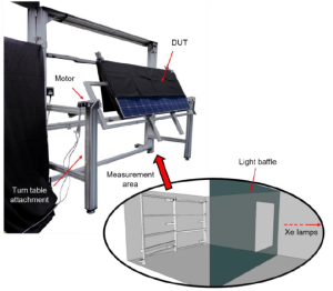
Angular response measurements can be implemented indoors or outdoors, nevertheless, outdoor angular response measurements can suffer from poor reproducibility because of the diffuse light component. Essentially the procedure is based on acquiring ISC measurements for the PV module under test over a range of angles of incidence. For indoor measurements a solar simulator is used and an apparatus that can accurately rotate the module is utilised, like the one presented in Figure 4. A recommended accuracy for the angle control is ± 1o, care should be taken that the rotational angle of the PV module does not change. Temperature and irradiance should be monitored during measurements. Isolating one cell of the module (destructive method) and implementing such measurements on this cell (while rotating the module) is acceptable.
Measurements should be applied towards both angular directions and symmetry of rotation should be verified at 80o and -80o rotation angles, the ISC value between these two positions should not differ more than 2 %. Angle steps of a maximum of 10o are recommended between -60o and 60o, while outside that range steps of 5o are more appropriate, due to the significant expected variations outside this range.
The outdoor testing procedure for angular response measurements involves gathering a set of ISC data of the test PV modules, with variable angle of incidence, while realising the necessary measurements in order to distinguish between the diffuse and beam components of the global irradiance. This includes the following components for implementing the measurements:
- A pyranometer mounted in the same plane as the module PV module under test.
- A PV reference device in conformance with IEC 60904-2 [12] to measure the global normal irradiance.
- A pyrheliometer in order to measure the direct normal component of irradiance.
- Temperature measurement of ambient temperature and module temperature.
- An apparatus to vary the angle of incidence on the module over the range of -90o to 90o. The determination of the angle of incidence with additional means is advised.
Ambient temperature, wind speed, incident irradiance and the mounting configuration all have an impact on the operating temperature of a PV module. The methodology to acquire the necessary coefficients to determine the Nominal Operating Module Temperature (NOMT) of a PV module involves measurement acquisition and specific procedures of data processing. The method is based on gathering actual PV module temperature data over a range of environmental conditions. The data obtained is averaged and analysed in a way that allows accurate and repeatable interpolation of the module temperature as a function of ambient temperature, irradiance and wind speed.
The temperature of the module (Tm) is primarily a function of the ambient temperature (Tamb), the wind speed (v) and the total solar irradiance (G) incident on the active surface of the module. The temperature difference (Tm – Tamb) is largely independent of the ambient temperature and is essentially linearly proportional to the irradiance at levels above 400 W⋅m–2.
The module temperature is modelled by (3): [math]\displaystyle{ T_m-T_{amb}=\frac{G}{u_0+u_1(\ v} }[/math]
Where u0 is the coefficient that describes the influence of the irradiance and u1 the coefficient of wind impact. Different PV modules technologies can have different u0 and u1 values, nevertheless, these differences usually have the same order of magnitude as the uncertainties of these values. Since the measured temperature varies depending on measurement conditions (sky temperature, round temperature, etc), a correction for the measured temperature may be required. In order to achieve this, two reference PV modules with known NMOT values are characterized in parallel with the device under test, during the same time period (minimum 6 months) and the average deviation from the 6-month NMOT values for the two reference modules is applied to the NMOT measurement for the device under test.
The measurement setup to realise the NMOT measurements consists of the following components:
- An open rack to support the test modules and a pyranometer or PV reference device in the
- An electronic maximum power point tracker (MPPT) or a resistive load to ensure that the module will operate near its maximum power point at STC.
- A pyranometer or PV reference device mounted in the plane of the test modules and within 0,3 m of the test array, accurate to at least ±5 %.
- Instrumentation to measure wind speed up to at least 10 m⋅s–1 and down to 0.25 m·s–1, installed approximately 0,7 m above the top of the modules.
- Ambient temperature sensor, with a time constant equal to or less than that of the modules, installed in a shaded enclosure with good ventilation near the wind sensor.
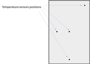
- Cell temperature sensors attached to the back side of the module, as shown in figure 5. The censors should be centred behind four solar cells approximately for wafer based technologies. An infrared camera can be used in order to avoid placing the sensors behind hot-spots, which will bias measurements.
- Data acquisition system to record irradiance, ambient temperature, module temperatures, wind speed within an interval of no more than 5 s
The test module should be installed with a tilt of 37,5° ± 2,5° and at least 0,6 m above ground level. There shall be a baffle of 2 module widths or 0,6 m (whichever is larger) beyond the module in both sides of the module when facing it. Measurements are realised on clear, sunny days and the parameters described above are recorded within a time interval of less than 1 s and all data shall be sampled every 5 s. The average of the 4 temperature sensors is calculated and data are rejected for the cases:
- When irradiance is below 400 W⋅m–2.
- For 10 min intervals after the irradiance varies by more than ±10 % from the maximum value to the minimum value during the preceding 10 min interval.
- For 10 min intervals after and during which a deviation of the instantaneous wind speed to below 0,25 m⋅s–1 or gusts larger than +200 % from a 5 min running average occurred.
- For data when the 5 min running average is less than 1 m⋅s–1 or greater than 8 m⋅s–1.
The average of the module temperatures at the four points is obtained and the difference between each of the four temperature sensors is calculated. The data of the sensor with the largest difference are rejected and the average is recalculated to acquire Tm. at least 10 different data points from at least 10 different days have to be acquired. Using all the available suitable data points and ensuring that data points from both before and after solar noon are utilized, average module-temperature is calculated in order to plot G/(Tm–Tamb) as a function of the 5 min average wind speed. Linear regression analysis is then used to determine the slope and intercept (u1 and u0) of the model. The coefficients are then used as specified in IEC 61215-2 to calculate the nominal module operating temperature (NMOT) [13].
For more information about the technical specifications and details regarding spectral response, angular response and NOMT measurements for energy rating, the reader is referred to the IEC 61853-2 standard.
Energy rating calculations and reference datasets
IEC 61853-3. Energy rating of PV modules
The procedures described in IEC 61853-3 provide a methodology to calculate the energy output (watt-hours) of a PV module, and the Climatic Specific Energy Rating (CSER) for a complete year at maximum power operation for the reference climatic profile(s) given in IEC 61853-4. The calculation requires the measurements described in IEC 61853-1 and IEC 61853-2 as inputs. Any degradation or instability effects of the PV module are not taken into account in this analysis.
The current methodology applies only to monofacial PV modules and not bifacial PV modules or BiPV. The procedures estimate the energy output (Wh) for every hour of a complete reference year, which is then used to estimate the CSER parameter. As defined earlier, the CSER parameter is the ratio of the actual energy output to that which would have been obtained if the PV module always performed with the energy conversion efficiency measured at STC. The input data for the energy rating calculations are:
- Matrix of Pmax versus irradiance and module temperature acquired as described in IEC 61853-1.
- The thermal coefficients u0, u1, which provide the PV module’s operating temperature as a function of irradiance and wind speed as described in IEC 61853-2.
- Angular response of the PV module as described in IEC 61853-2.
- Spectral responsivity of the PV module (IEC 61853-2), which is used to calculate any spectral mismatch effects and correct to the reference spectral conditions.
- The standard reference climatic profiles provided by IEC 61853-4
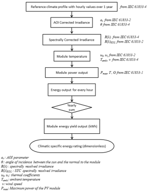
The full methodology is illustrated in the simplified flow chart of Figure 6 and concatenates the various models in order to calculate for every hour two sets of data:
- The effectively absorbed in-plane irradiance corrected for the angle of incidence and spectral effects.
- The temperature reached by the module.
The module peak power and energy output for a particular time step is then determined and the PV module energy output is calculated per hour. These individual hourly energy values are then summed over the data set to determine the annual energy production.
The climatic specific energy rating CSER can be finally calculated by the equation (2): [math]\displaystyle{ CSER=\frac{E_{mod,year}\bullet G_{ref}}{P_{max,STC}\bullet H_p} }[/math]
Where Hp is the total of the hourly global in-plane irradiance values G for the reference climatic period (1 year) from IEC 61853-4, Gref = 1000 W m‑2 is the irradiance STC, Pmax,STC is the maximum power at STC, taken from the power measurements acquired according to according to IEC 61853-1.
IEC 61853-4. Standard reference climatic profiles
In IEC 61853-4 six reference climatic datasets are used to describe the most representative working conditions that PV installations will encounter worldwide. They are described as:
- Tropical humid
- Subtropical arid
- Subtropical coastal
- Temperate coastal
- High elevation (above 3000m)
- Temperate continental
The datasets contain hourly values for one year of the variables necessary for Energy Rating calculations. These variables are:
- Year
- Month
- Day
- Hour (local solar time)
- Ambient temperature (Tamb)
- Wind speed at module height (v)
- Sun elevation
- Sun angle of incidence (to the normal of the module) (θ)
- Global horizontal irradiance (Gh)
- Direct horizontal irradiance (Bh)
- Global in-plane irradiance (G)
- Direct in-plane irradiance (B)
- Spectrally resolved global in-plane irradiance (W/m2) for a set of discrete bands
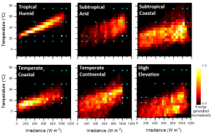
Figure 7 illustrates the distribution of total energy for the different operating conditions for the six reference climates, for monocrystalline silicon module technology. This indicates how PV modules can be optimised in order to maximise the energy rating for particular climates. For example, for the “tropical arid” and “subtropical arid” climates, it is important that a module operates well at high temperatures (50 °C), while for the “temperate coastal” reference climate, there is a large concentration of energy generated at around 200Wm−2 irradiance and temperatures between 10 and 20 °C [14]. For more information on the uncertainties of energy rating calculations, the reader is referred to [14].
Additional considerations regarding the IEC 61853 standard series and bifacial PV devices
The scope of the IEC 61853 is limited at the moment to mono-facial and single-junction devices. Nevertheless, commercial bifacial PV module products are becoming more widespread and additional BiPV products are introduced. The main considerations when assessing the specific considerations required in order to create an extended energy rating procedure for additional products and system configurations are:
- Mounting scenarios: at present the standard considers the modules located facing the equator and with an inclination angle of 20°. However, the current application trends of bi-facial and BIPV include vertical east-west racks and other installation options such as horizontal single-axis trackers (HSAT). The need to add a new set of mounting scenarios should be verified.
- New inputdatasets:
- The rear-side irradiance is not included at present in the defined standard climatic profiles and therefore not considered in the energy rating procedure. However, the albedo should be defined and provided for use in applications involving bi-facial modules, either on stand-alone systems or integrated into the built environment.
- The in-plane irradiance values and the angle of incidence between the solar direct radiation and the module's surface would also need to be provided for the new set of mounting scenarios representative of the current trend of bi-facial and BIPV installation options.
- Spectral correction factor: to introduce a new definition including the spectral response at the rear of the module and the spectral albedo beneath the module. The rear-side irradiance is not included in the current version of the standard.
- Power matrix: a new definition and methodology on how to measure the power matrix for bi-facial modules needs to be discussed and agreed.
- Thermal dynamics:
- Higher working temperatures are often found in BIPV devices as compared to free standing modules. The power matrix described in IEC 61853-1 might be extended with additional points covering higher temperatures.
- The methodology defining the thermal coefficients used when estimating the working temperature of BIPV modules (coefficients u0 and u1 described in IEC 61853-2) should be investigated and validated.
- Patterned textures, aesthetic coatings or special foils with non-uniform appearance might induce thermal gradients along the PV module. Further investigations are required in order to assess the potential use of more suitable thermal models.
References – Further reading
[1] International Electrotechical Commission, “IEC 60904-3 Photovoltaic devices - Part 3: Measurement principles for terrestrial photovoltaic (PV) solar devices with reference spectral irradiance data,” 2019.
[2] D. Dirnberger, B. Müller, and C. Reise, “PV module energy rating: Opportunities and limitations,” Prog. Photovoltaics Res. Appl., vol. 23, no. 12, pp. 1754–1770, 2015.
[3] W. Herrmann, M. Schweiger, and L. Rimmelspacher, “Solar Simulator Measurement Procedures for Determination of the Angular Characteristic of PV Modules,” in 29th European Photovoltaic Solar Energy Conference (29th EU PVSEC), 2014, pp. 2403–2406.
[4] International Electrotechnical Commission, “IEC 61853-3 Photovoltaic (PV) module performance testing and energy rating Part 3: Energy rating of PV modules,” 2018.
[5] International Electrotechnical Commission, “IEC 61853-1 Photovoltaic (PV) module performance testing and energy rating Part 1: Irradiance and temperature performance measurements and power rating,” 2011.
[6] International Electrotechnical Commission, “IEC 61853-2 Photovoltaic (PV) module performance testing and energy rating Part 2: Spectral response, incidence angle and module operating temperature measurements,” 2016.
[7] International Electrotechnical Commission, “IEC 61853-4 Photovoltaic (PV) module performance testing and energy rating Part 4: Standard reference climatic profiles,” 2018.
[8] International Electrotechical Commission, “IEC 60891 Photovoltaic devices – Procedures for temperature and irradiance corrections to measured I-V characteristics,” 2009.
[9] International Electrotechnical Commitee, “IEC 60904-8 Photovoltaic devices - Part 8: Measurement of spectral responsivity of a photovoltaic (PV) device,” 2014.
[10] S. Winter et al., “Design, realization and uncertainty analysis of a laser-based primary calibration facility for solar cells at PTB,” Measurement, vol. 51, no. 1, pp. 457–463, May 2014.
[11] H. B. M. N. Al Husna, “Characterisation of Spectral and Angular Effects on Photovoltaic Modules for Energy Rating,” Loughborough University, 2018.
[12] International Electrotechnical Commitee, “IEC 60904-2 Photovoltaic Devices Part 2: Requirements for photovoltaic reference devices,” 2015.
[13] International Electrotechnical Commission, “IEC 61215-2: Terrestrial Photovoltaic (PV) Modules – Design Qualification and Type Approval -Part 2: Test procedures,” 2016.
[14] J. C. Blakesley et al., “Accuracy, cost and sensitivity analysis of PV energy rating,” Sol. Energy, vol. 203, no. March 2019, pp. 91–100, Jun. 2020.

